


Active Topics
-
Firefox with Leste (5)
to Maemo 7 / Leste by teroyk - 4 days, 7 hrs ago -
Handbook (2)
to Maemo 7 / Leste by teroyk - 5 days, 6 hrs ago - more...


|
2012-05-22
, 04:19
|
|
Posts: 138 |
Thanked: 80 times |
Joined on Apr 2012
|
#122
|
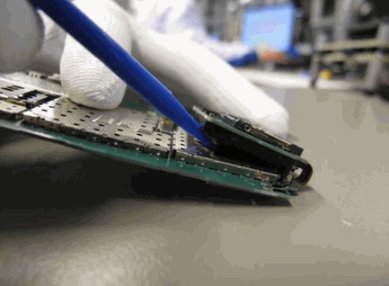
dear frind i am showing u corect method how to repair usb
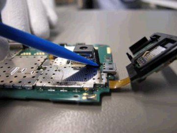
Make sure the flex between main PWB and SD-support PWB IS NOT BEND OR TWISTED SIDEWAYS.
after
Remove the old SD support adhesive tape from the shield carefully with the same plastic stick
Remove old SD support adhesive tape from the SD-memory card PWB package
Make sure the flex to SD-support PWB IS NOT BEND OR TWISTED SIDEWAYS.
Clean the adhesive areas.
 |
|
2012-05-22
, 09:52
|
|
Posts: 5,028 |
Thanked: 8,613 times |
Joined on Mar 2011
|
#123
|
WTF is that, some kind of auto, semi-intelligent spam?
__________________
N900's aluminum backcover / body replacement
-
N900's HDMI-Out
-
Camera cover MOD
-
Measure battery's real capacity on-device
-
TrueCrypt 7.1 | ereswap | bnf
-
Hardware's mods research is costly. To support my work, please consider donating. Thank You!
N900's aluminum backcover / body replacement
-
N900's HDMI-Out
-
Camera cover MOD
-
Measure battery's real capacity on-device
-
TrueCrypt 7.1 | ereswap | bnf
-
Hardware's mods research is costly. To support my work, please consider donating. Thank You!
| The Following 2 Users Say Thank You to Estel For This Useful Post: | ||
|
|
2012-06-09
, 09:07
|
|
Posts: 12 |
Thanked: 7 times |
Joined on May 2011
|
#124
|
Great information guys!!
I just repaired my constantly failing USB connector. Near to trash all the phone. Tired about this sh**.
Really, we can be honest, it is not the best phone of the world. I do a mistake buying it. But now I have it and if I have it I want to use it.
I'm technician and know how to do that kind of works but I don't have all the knowledge and information. Just your pictures about the 5V location and your demonstration of what know and using my brain was the power I just got it!
Trying to repair it I damaged the copper in the 5V pin. So I missed that. Now I just take a piece of a copper wire from a electrical wire and with that little thing I jumped from the connector to the 5 Volts (above the SMD component). Thank you very much guys!
Just to take in account I want to suggest to new people trying to do it:
1- Make your space for work. Put the PCB of the phone in a table or piece of wood. A little (sized to at least two PCBs) piece of MDF is enough.
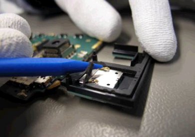
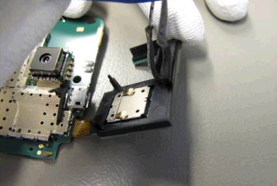
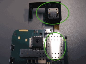
Take off the micro SD card reader. Just as you can see in the pictures in this post (messages above). Press and sustain it with something so you can work without you bothering.
2- Reinforce the connector itself. You will need a powerful solder iron (100 Watts). With a sandpaper scrapes off the varnish near the metal of the connector (just to give it more space in each side where you can). Don't try to scrap in difficult places. Do it softly and with attention trying to don't damage near components.
Then begin to solder with a 100 watts solder iron. Ensure to heat well but not too much (you can damage near components if you do it during a long time = 20 seconds. In that case stop and wait until it cold, then retry). Heat the connector and apply solder wire, enough to cover all the side of the connector but not to cover the connector itself (you can ruin it).
You must sustain the connector with a gripper or something appropriate for that. You must sustain it before you heat it and after it becomes cold.
If you don't sustain it, it may be loose and welding will be of poor quality.
So, to ensure you soldered it well you must sustain it firmly from where you see the solder smelted like liquid and after you feel it near cold (and solid).
That will be a good welding.
3- Make more space for work with the pins now. Take out the metal plate (a lid) that covers the chip. With some screwdriver and a gripper you can help.
With a pliers or something like that you must cut the metal that cover your space to work with the connector (not the lid, you must cut the metal soldered to PCB that crimped with the lid).
Cut only that piece so you can put later the lid newly. Try to don't damage nothing, be careful doing that.
Now you must straighten a little piece of metal from the connector (the piece that covers the back of the connector). While you try to straight it, it will cut off. No problem, just leave it so, we don't need any more that fu**** piece of metal. That just cover us from seeing the pins.
Follow the instructions of the old messages in this post for understand it better.
I just wrote this to take in account not for the only and final elite solution. Take in account my suggestions but search for more information too.
4- For reworking / soldering the pins use a small soldering iron. Don't use the 100 Watts one!! Use a + - 40 watts soldering iron. I used a regulated temperature soldering iron with a very tiny tip so I can put it in the very little pins and very near spaces without touching anything except the pins.
A guy modified a standard soldering iron tip just adding a copper wire coiled around it. That was a good idea!
If you can get something like that (a tiny tip), you don't need to disassemble the camera. I prefer to disassemble the less things what I can. Each thing what you disassemble can becomes damaged or malfunction. And gives you more work.
5- Take in account that if you melt a lot of solder wire over the pins here are the solution!!:
Don't try to force nothing, that will be worst.
Use some resin. Just put your solder iron in the resin and rapidly heat the melted pins. Magically they will separate!
I was near to losing all because that (melted pins). And just give a opportunity to resin. Luckily that was the solution!
As a security measure always use resin for finish your work. Next that you can be secure about nothing is touching that don't must and all that must be soldered will be.
6- Protect the flex of the screen.
I used a soft napkin paper (from kitchen or bath room :P) or you can use cotton too. Take a spray of "four in one" oil and moisten the paper/cotton a little. Now pass it over the metal where the ribbon slides. Try to moisten the metal. Repeat If you need more oil.
Use the oil to clean some metal pieces too (external not internal, don't use oil for internal components/pieces!!). Don't put it in excess, it must be superficial but in the place where the flex slides you can put a little more.
The flex can wear from use. If you use oil it can have more lifetime.
7- With that kind of oil you can clean too the lens. Because it is a very refined oil (WD40). If you use a thicker oil you cannot use it for cleaning lens. Only WD40 worked for me. And the results are amazing. You can clean the viewer of the camera. You can clean the screen and so on.
Of course, use it for moisture, next with a hyssop (that you use for cleaning your ear) you can clean the lenses and pass it very times as you need / see the lens clean. With the hyssop or a cotton you will quit the excess of oil. Do it after you don't observe presence of oil (you will feel more friction in the cotton). And in meantime you can see how it becomes clean and more clean (I managed to leave it so clean that it seemed there was nothing, even a glass).
Of course there were some hairs/rests of cotton so I used a very little gripper (for electronics) to take that. You can use a clip of wax small.
8- If you have problems in the USB. There some things to consider:
You can have shortcircuited the both pins of data (the middle ones). The symptoms are: The phone can be charged with the wall charger and with computer but cannot detect the computer and the computer don't detect it. That is because Nokia use the two pins of data short for a charger.
Your phone charges and is detected a lot of times in the computer but never work as USB storage. I just received it in syslog:
usb 5-2: new full speed USB device number 47 using ohci_hcd
usb 5-2: new full speed USB device number 48 using ohci_hcd
usb 5-2: new full speed USB device number 49 using ohci_hcd
usb 5-2: new full speed USB device number 50 using ohci_hcd
usb 5-2: new full speed USB device number 51 using ohci_hcd
usb 5-2: new full speed USB device number 52 using ohci_hcd
That is because you have one data pin shortcircuited to ground.
Your phone don't charge and when you move the connector it charges but not last too much. It is because you have the pins desoldering. You must proceed to repair your connector.
Some problems related to USB disconnections or slowdowns maybe the phone connector but too the PC connector (not soldering problems but poor quality specially the front ones).
I think the connector of this phone is the worst in the world.
I have repaired it now but anyway it is not perfect and sometimes it fails, specially with:
usb 2-5: reset high speed USB device number 2 using ehci_hcd
It never worked correctly, always had some errors.
Well. That is all, folks :P
I just repaired my constantly failing USB connector. Near to trash all the phone. Tired about this sh**.
Really, we can be honest, it is not the best phone of the world. I do a mistake buying it. But now I have it and if I have it I want to use it.
I'm technician and know how to do that kind of works but I don't have all the knowledge and information. Just your pictures about the 5V location and your demonstration of what know and using my brain was the power I just got it!
Trying to repair it I damaged the copper in the 5V pin. So I missed that. Now I just take a piece of a copper wire from a electrical wire and with that little thing I jumped from the connector to the 5 Volts (above the SMD component). Thank you very much guys!
Just to take in account I want to suggest to new people trying to do it:
1- Make your space for work. Put the PCB of the phone in a table or piece of wood. A little (sized to at least two PCBs) piece of MDF is enough.
Take off the micro SD card reader. Just as you can see in the pictures in this post (messages above). Press and sustain it with something so you can work without you bothering.
2- Reinforce the connector itself. You will need a powerful solder iron (100 Watts). With a sandpaper scrapes off the varnish near the metal of the connector (just to give it more space in each side where you can). Don't try to scrap in difficult places. Do it softly and with attention trying to don't damage near components.
Then begin to solder with a 100 watts solder iron. Ensure to heat well but not too much (you can damage near components if you do it during a long time = 20 seconds. In that case stop and wait until it cold, then retry). Heat the connector and apply solder wire, enough to cover all the side of the connector but not to cover the connector itself (you can ruin it).
You must sustain the connector with a gripper or something appropriate for that. You must sustain it before you heat it and after it becomes cold.
If you don't sustain it, it may be loose and welding will be of poor quality.
So, to ensure you soldered it well you must sustain it firmly from where you see the solder smelted like liquid and after you feel it near cold (and solid).
That will be a good welding.
3- Make more space for work with the pins now. Take out the metal plate (a lid) that covers the chip. With some screwdriver and a gripper you can help.
With a pliers or something like that you must cut the metal that cover your space to work with the connector (not the lid, you must cut the metal soldered to PCB that crimped with the lid).
Cut only that piece so you can put later the lid newly. Try to don't damage nothing, be careful doing that.
Now you must straighten a little piece of metal from the connector (the piece that covers the back of the connector). While you try to straight it, it will cut off. No problem, just leave it so, we don't need any more that fu**** piece of metal. That just cover us from seeing the pins.
Follow the instructions of the old messages in this post for understand it better.
I just wrote this to take in account not for the only and final elite solution. Take in account my suggestions but search for more information too.
4- For reworking / soldering the pins use a small soldering iron. Don't use the 100 Watts one!! Use a + - 40 watts soldering iron. I used a regulated temperature soldering iron with a very tiny tip so I can put it in the very little pins and very near spaces without touching anything except the pins.
A guy modified a standard soldering iron tip just adding a copper wire coiled around it. That was a good idea!
If you can get something like that (a tiny tip), you don't need to disassemble the camera. I prefer to disassemble the less things what I can. Each thing what you disassemble can becomes damaged or malfunction. And gives you more work.
5- Take in account that if you melt a lot of solder wire over the pins here are the solution!!:
Don't try to force nothing, that will be worst.
Use some resin. Just put your solder iron in the resin and rapidly heat the melted pins. Magically they will separate!
I was near to losing all because that (melted pins). And just give a opportunity to resin. Luckily that was the solution!
As a security measure always use resin for finish your work. Next that you can be secure about nothing is touching that don't must and all that must be soldered will be.
6- Protect the flex of the screen.
I used a soft napkin paper (from kitchen or bath room :P) or you can use cotton too. Take a spray of "four in one" oil and moisten the paper/cotton a little. Now pass it over the metal where the ribbon slides. Try to moisten the metal. Repeat If you need more oil.
Use the oil to clean some metal pieces too (external not internal, don't use oil for internal components/pieces!!). Don't put it in excess, it must be superficial but in the place where the flex slides you can put a little more.
The flex can wear from use. If you use oil it can have more lifetime.
7- With that kind of oil you can clean too the lens. Because it is a very refined oil (WD40). If you use a thicker oil you cannot use it for cleaning lens. Only WD40 worked for me. And the results are amazing. You can clean the viewer of the camera. You can clean the screen and so on.
Of course, use it for moisture, next with a hyssop (that you use for cleaning your ear) you can clean the lenses and pass it very times as you need / see the lens clean. With the hyssop or a cotton you will quit the excess of oil. Do it after you don't observe presence of oil (you will feel more friction in the cotton). And in meantime you can see how it becomes clean and more clean (I managed to leave it so clean that it seemed there was nothing, even a glass).
Of course there were some hairs/rests of cotton so I used a very little gripper (for electronics) to take that. You can use a clip of wax small.
8- If you have problems in the USB. There some things to consider:
You can have shortcircuited the both pins of data (the middle ones). The symptoms are: The phone can be charged with the wall charger and with computer but cannot detect the computer and the computer don't detect it. That is because Nokia use the two pins of data short for a charger.
Your phone charges and is detected a lot of times in the computer but never work as USB storage. I just received it in syslog:
usb 5-2: new full speed USB device number 47 using ohci_hcd
usb 5-2: new full speed USB device number 48 using ohci_hcd
usb 5-2: new full speed USB device number 49 using ohci_hcd
usb 5-2: new full speed USB device number 50 using ohci_hcd
usb 5-2: new full speed USB device number 51 using ohci_hcd
usb 5-2: new full speed USB device number 52 using ohci_hcd
That is because you have one data pin shortcircuited to ground.
Your phone don't charge and when you move the connector it charges but not last too much. It is because you have the pins desoldering. You must proceed to repair your connector.
Some problems related to USB disconnections or slowdowns maybe the phone connector but too the PC connector (not soldering problems but poor quality specially the front ones).
I think the connector of this phone is the worst in the world.
I have repaired it now but anyway it is not perfect and sometimes it fails, specially with:
usb 2-5: reset high speed USB device number 2 using ehci_hcd
It never worked correctly, always had some errors.
Well. That is all, folks :P
|
|
2012-06-09
, 09:19
|
|
Posts: 12 |
Thanked: 7 times |
Joined on May 2011
|
#125
|
Originally Posted by geneven

What I mean is, other threads have implied that soldering is totally easy and anyone could do it with no difficulty.This thread shows that not only are problems possible, permanently damaging the N900 is one possible outcome.
That is because if you don't need to solder the pins you need only to reinforce the connector. And that is not too difficult to do. But you must do that soon if your connector get out of place. If not you will need to solder the pins too. And that is the hard/dangerous part.
|
|
2012-06-09
, 12:13
|
|
Posts: 5,028 |
Thanked: 8,613 times |
Joined on Mar 2011
|
#126
|
Originally Posted by anyeos
Honestly? It is. At least, if You want to have mobile computer with mobile phone function
Really, we can be honest, it is not the best phone of the world.

__________________
N900's aluminum backcover / body replacement
-
N900's HDMI-Out
-
Camera cover MOD
-
Measure battery's real capacity on-device
-
TrueCrypt 7.1 | ereswap | bnf
-
Hardware's mods research is costly. To support my work, please consider donating. Thank You!
N900's aluminum backcover / body replacement
-
N900's HDMI-Out
-
Camera cover MOD
-
Measure battery's real capacity on-device
-
TrueCrypt 7.1 | ereswap | bnf
-
Hardware's mods research is costly. To support my work, please consider donating. Thank You!
| The Following User Says Thank You to Estel For This Useful Post: | ||
 |
|
2012-06-09
, 13:21
|
|
Posts: 435 |
Thanked: 684 times |
Joined on Apr 2012
@ Netherlands 020
|
#127
|
Originally Posted by anyeos
Could you please tell use which phone/tablet would do better than this one?
Really, we can be honest, it is not the best phone of the world. I do a mistake buying it.
|
|
2012-06-09
, 13:26
|
|
Posts: 5,028 |
Thanked: 8,613 times |
Joined on Mar 2011
|
#128
|
NO!
Absolutely no for changing this thread into another "mine is better than yours". We already know the usual arguments of Android kids and iSheeps, no need to rewrite them here again.
/Estel
Absolutely no for changing this thread into another "mine is better than yours". We already know the usual arguments of Android kids and iSheeps, no need to rewrite them here again.
/Estel
__________________
N900's aluminum backcover / body replacement
-
N900's HDMI-Out
-
Camera cover MOD
-
Measure battery's real capacity on-device
-
TrueCrypt 7.1 | ereswap | bnf
-
Hardware's mods research is costly. To support my work, please consider donating. Thank You!
N900's aluminum backcover / body replacement
-
N900's HDMI-Out
-
Camera cover MOD
-
Measure battery's real capacity on-device
-
TrueCrypt 7.1 | ereswap | bnf
-
Hardware's mods research is costly. To support my work, please consider donating. Thank You!
| The Following User Says Thank You to Estel For This Useful Post: | ||
|
|
2012-06-09
, 13:30
|
|
Posts: 435 |
Thanked: 684 times |
Joined on Apr 2012
@ Netherlands 020
|
#129
|
Originally Posted by Estel
OK sorry man.
NO!
Absolutely no for changing this thread into another "mine is better than yours". We already know the usual arguments of Android kids and iSheeps, no need to rewrite them here again.
/Estel
BTW
Thanks for the debian chroot image

| The Following User Says Thank You to jellyroll For This Useful Post: | ||
|
|
2012-06-13
, 13:44
|
|
Posts: 28 |
Thanked: 46 times |
Joined on Apr 2012
|
#130
|
Originally Posted by pablocrossa
Yes, it's a bit late for that. I gave up and already bought a used N900 with a working port and transplanted all the SD and eMMC contents to it so it's identical to my old phone in every way.
I know this is old but maybe this helps. I would Imagine (I am supposing here) that your data pins are soldered to close together and somehow interfere or that one of your data is soldered to close to the voltage or ground:
Nokia chargers shortcut the data+ and data- pins so it knows it is a charger. Maybe if it does not show i with your computer its because those pins are shorting themselves. Something similar could be happening when plugging into the charger, it might be shorting with one of the data ports and hence disconnects.
I want to believe that your data- is touching/shorting the ground (or voltage- in some places) and hence it messes up. Give it a look and come back with anything
But I will take your advice into consideration if I ever get the courage to get soldering the old phone again.
Originally Posted by anyeos
Good tutorial, mate! If only you'd have pics with that one, it would be worth putting on instructables.com (no endorsing here, carry on)
That is because if you don't need to solder the pins you need only to reinforce the connector. And that is not too difficult to do. But you must do that soon if your connector get out of place. If not you will need to solder the pins too. And that is the hard/dangerous part.
Last edited by gebeleysis; 2012-06-13 at 13:58.
All I want is 40 acres, a mule, and Xterm.